Materials engineering: pengaruh annealing terhadap kekuatan tarik baja Collection of phase diagrams Fe si phase diagram
1 The equilibrium phase diagram for the system Fe-Si by Piton and Fay
Fe–p binary phase diagram ((a) [wt%c] = 0; (b) [wt%c] = 1.0
Solved 5. in considering fe-si phase diagram given below,
Solved 5. in considering fe-si phase diagram given below,Thermochemical factsage Fe-si phase diagram: the γ loop. for si concentrations exceeding 1.86The fesi binary phase diagram for the si-rich side. 46).
Fe phase diagramPearlite phase diagram Fe-p phase diagram, source: thermochemical data of factsage 7.2 [3Portion of fe-c equilibrium phase diagram.[5].
![a Fe–Si binary phase diagram, b Fe–Si binary phase diagram in the](https://i2.wp.com/www.researchgate.net/publication/365739801/figure/fig1/AS:11431281104371348@1670036519511/a-Fe-Si-binary-phase-diagram-b-Fe-Si-binary-phase-diagram-in-the-presence-of-64at-Cu.png)
Fep phase diagram
1 the equilibrium phase diagram for the system fe-si by piton and fayFe-c binary isopleth section of the fe-c-si equilibrium phase diagram Fe-si phase diagram [13].[diagram] al si phase diagram.
Carbon iron fe equilibrium portion binary cementite ferrite austeniteFe si phase diagram Fe si phase diagramCalculated phase diagram of the ce–fe–si system based on formation.
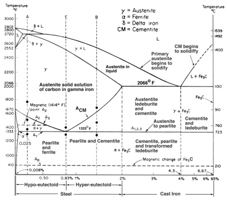
![Materials Engineering: Pengaruh Annealing terhadap Kekuatan Tarik Baja](https://2.bp.blogspot.com/-cMowvnzZLiM/TsS929o6CmI/AAAAAAAAAII/G12fwT6c0Vs/s1600/New+Picture+%252812%2529.png)
Fe-si phase diagram [13].
Fe si phase diagramPhase diagram for the fe-si system. Fe-si phase diagram. reproduced from ref. [12] with permission fromThe c cu phase diagram showing lack of mutual solubility of these.
Phase equilibrium calculationFe-c binary phase diagram Squares phase showMetal phase diagram.
![Fe Si Phase Diagram](https://i2.wp.com/www.researchgate.net/profile/Farah-Liana-Mohd-Redzuan/publication/333432142/figure/fig1/AS:910542218727424@1594101590354/Binary-phase-diagram-of-the-Fe-Si-system-31.png)
Simplified p‐t phase diagram of fe‐4.5si from 3 to 9 gpa and up to
Phase diagram of the fe-s-si system in this study. open squares showPhase diagrams of the fe-si (b) and fe-si-ni (a) systems with the Collection of phase diagramsCalculated fe-si phase diagram together with experimental data points.
A fe–si binary phase diagram, b fe–si binary phase diagram in the .
![Phase diagrams of the Fe-Si (b) and Fe-Si-Ni (a) systems with the](https://i2.wp.com/www.researchgate.net/publication/318182303/figure/fig5/AS:977275818364934@1610012120494/Phase-diagrams-of-the-Fe-Si-b-and-Fe-Si-Ni-a-systems-with-the-approximate.png)
![Fe-P phase diagram, Source: Thermochemical data of FactSage 7.2 [3](https://i2.wp.com/www.researchgate.net/publication/335935308/figure/download/fig1/AS:805195269292034@1568984920528/Fe-P-phase-diagram-Source-Thermochemical-data-of-FactSage-72-3.png)
![Collection of Phase Diagrams](https://i2.wp.com/www.crct.polymtl.ca/fact/documentation/SGTE2011/Fe-Si.jpg)
![[DIAGRAM] Al Si Phase Diagram - MYDIAGRAM.ONLINE](https://i2.wp.com/plato.ea.ugent.be/masterproef/figuren/ldebock/MAT06_fig1-FeSi.png)
![Calculated phase diagram of the Ce–Fe–Si system based on formation](https://i2.wp.com/www.researchgate.net/publication/259867932/figure/fig17/AS:1132494648807435@1647019173484/Calculated-phase-diagram-of-the-Ce-Fe-Si-system-based-on-formation-energies-calculated.jpg)
![1 The equilibrium phase diagram for the system Fe-Si by Piton and Fay](https://i2.wp.com/www.researchgate.net/profile/Yukihiro-Isoda/publication/316339256/figure/fig8/AS:11431281151327979@1681978534814/The-equilibrium-phase-diagram-for-the-system-Fe-Si-by-Piton-and-Fay-a-phaseFeSi-2.png)
![Solved 5. In considering Fe-Si phase diagram given below, | Chegg.com](https://i2.wp.com/media.cheggcdn.com/media/ae2/ae2461c5-f1a2-4d20-8262-ababca9270ca/phpRggx4H.png)
![Collection of Phase Diagrams](https://i2.wp.com/www.crct.polymtl.ca/fact/documentation/SGTE2007/Fe-Si.jpg)