Circuit capacitive inductive cos Purely capacitive circuit phasor diagram Phasor diagram of capacitor
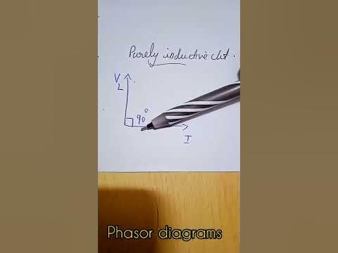
Phasor diagrams of purely resistive, inductive and capacitive circuits
Why power in pure inductive and pure capacitive circuit is zero?
40 phasor diagram rlc circuit
Phasor diagram of capacitorWhat is a pure capacitor circuit phasor diagram and waveform circuit The current in an inductive circuitPhasor diagram of capacitor in ac circuit.
What is the symbol for inductive reactance at graham odell blog27 the correct phasor diagram pure capacitive ac circuit is → vc b) iv. r Ac capacitance inductance phasor diagram circuit inductive capacitive reactance analysis gif physics emoCapacitive capacitance capacitor reactance shift inductive relation sinusoidal ws wave waveforms leads acting alternate linquip electrical capacitors.

Capacitor phasor diagram
Solved the diagram represents a: a.pure capacitivePhasor representation of one phase ac circuit presentation What is capacitive circuit? formula & functionUnderstanding the phasor diagram for a capacitive circuit: a visual guide.
Phasor circuit rlc series diagram voltage current ac power draw phase impedance triangle reactive angle phasors calculate physics lagging lengthPurely resistive, purely inductive and purely capacitive circuits for jee Diagram circuit pure capacitive represents phasor resistive inductive question waveformsDraw the time.

Find out the phase relationship between voltage and current in a pure
Circuit pure capacitor diagram capacitive phasorWhat is rlc series circuit? Phasor diagram of capacitorWhat is a pure capacitor circuit?.
Phasor diagram of capacitorPhasor diagram of rc series circuit How to draw a phasor diagram for pure capacitive circuit #shorts #Phasor diagrams of purely resistive, inductive and capacitive circuits.

Ac circuit containing capacitor only
Capacitor phasor diagramWhat is a power triangle? active, reactive & apparent power Ac capacitance and capacitive reactance in ac circuitWhat is power factor?.
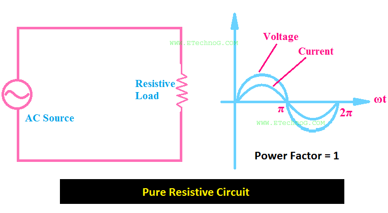
Phasor diagram of purely resistive circuit27 the correct phasor diagram pure capacitive ac circuit is → vc b) iv. r Inductor in circuit diagramCapacitive phasor.